5 Decision Service Usage Patterns
Blog: Method & Style (Bruce Silver)
One of the most significant aspects of DMN 1.2 is the establishment of decision services as an an important and useful feature of the standard. Decision services existed previously but offered little practical utility other than demarking units of execution within a DRD. Today that is just one of five distinct usage patterns for DMN decision services.
Usage Pattern 1: As a unit of deployment
Perhaps the most important use of decision services is not even mentioned in the spec, but it is implicit in DMN’s architecture and a major theme of DMN Cookbook. A decision model in which all nodes have defined decision logic can be deployed into the runtime environment as a stateless service. In the Trisotech tool, for instance, this requires just a single mouse click. The service can be invoked by any client app or process capable of making a REST call. If you want to see this in action, check out this demo of a DMN-based stock market timing app from bpmNEXT.
Usage Pattern 2: As a unit of execution
This was the original decision service idea from DMN 1.1, applicable to decision models executable in multiple steps. A familiar example of this is the Lending example from the DMN spec. Approving or declining the loan involves at least three steps:
- A prequalification decision to determine the type of credit information required to process the application;
- If the application is not declined at step 1, an approval decision using the obtained credit information;
- If step 2 is inconclusive, a human adjudication decision.
Although the example is described by a single DRD, its multi-step nature is revealed only by a companion BPMN (process) model. Readers of my DMN Method and Style know that I have long had a problem with this. A process model should not be required to understand a decision model. If the intent is that the decision requires multiple steps, that should be revealed by the DMN model alone.
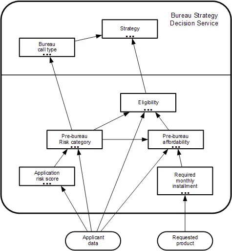
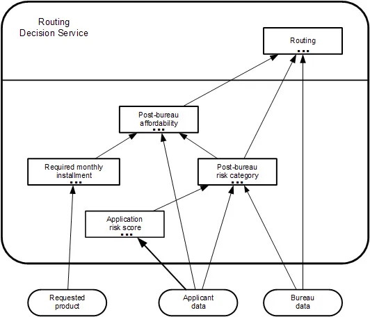
Decision services allow that to happen. In the DMN notation, a decision service is represented by a rounded rectangle with thick border enclosing the decision nodes comprising the service, meaning that fragment of the DRD is executed as a unit. A horizontal line bisecting the shape separates output decisions, which return their value upon service execution, from “encapsulated” decisions, which do not. Incoming information requirements crossing the shape boundary define the service’s parameters.
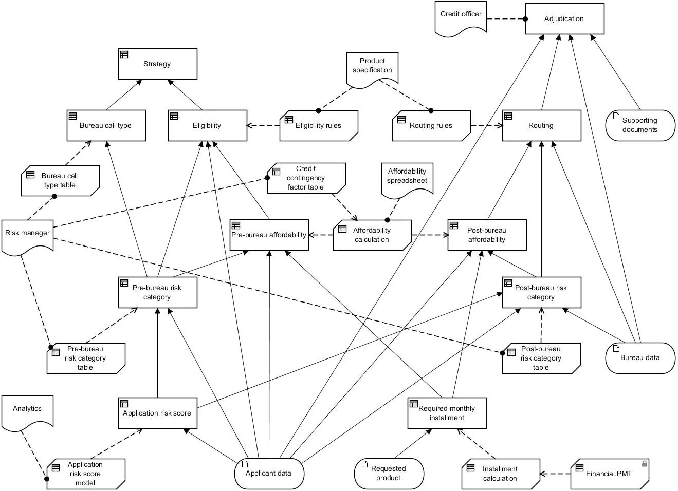
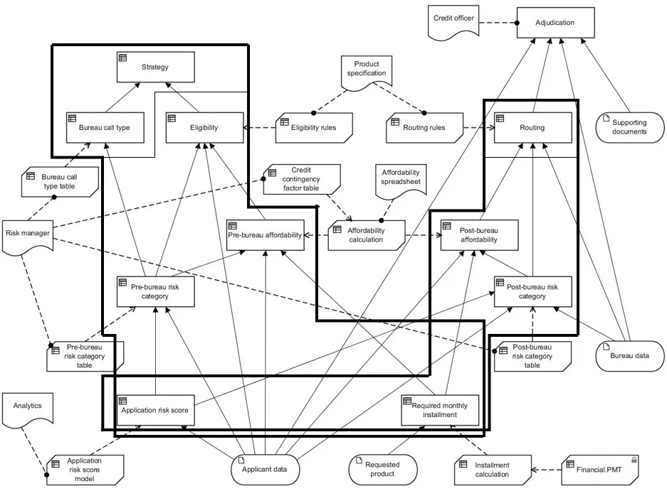
The decision service shape is an overlay on the DRD. The service does not “own” its enclosed elements. A single decision node, for example, could be part of more than one decision service. Such a rectangular overlay, while conceptually simple, makes drawing the DRD virtually impossible, especially when a decision node is shared by multiple services. A freeform polygon shape, as shown below, is more practical.
For that reason, the DMN spec does not even try to overlay the decision service shapes on this DRD, instead revealing the services in completely separate DRDs. The ellipses at the bottom of the decisions in these DRDs is supposed to mean that some information requirements or knowledge requirements are not displayed.
Usage Pattern 3: As a unit of reusable logic
In DMN 1.1, a decision service could be invoked only by an external client, but DMN 1.2 allows also invocation by a decision or BKM. As such, the service is like a BKM, a unit of reusable decision logic. Commonly used logic functions can be saved in libraries, imported into a decision model and invoked there, promoting standardization and code reuse across the organization. While using BKMs in this way existed in DMN 1.1, importing external elements had technical issues that prevented proper implementation. Those have been fixed in DMN 1.2, and invoking BKMs and decision services now both work in essentially the same way.
In this usage pattern, decision services enjoy one business-friendliness advantage over BKMs. A BKM is a single DRG element, so if its logic is complex it must be modeled as a context, a list of context entries and a final result. I’ve never understood why, but many so-called experts have declared contexts NOT business-friendly. The logic of a complex decision service, on the other hand, is defined as a DRD, which those people claim is much friendlier.
Usage Pattern 4: As a unit of delegated implementation
This usage pattern is similar to the previous one, but its motivation is different. It comes from methodologies in which business users create decision requirements (i.e., the DRD) and then hand them off to technical modelers for implementation. A number of tools support DRDs but use their own proprietary language for decision logic, creating a thin standards-based veneer over what is still a proprietary language. A better approach, consistent with the DMN standard, is for the technical modeler to create a DMN decision service implementing the required decision logic, and invoked by the original decision in the DRD. Here it is not about logic reuse, so the service is not saved off to (and imported from) an external library, but is added to the original decision model.
Again, this allows decision services to play a role formerly reserved for BKMs. I used to wonder why the Lending example in the spec had so many BKMs where there was no apparent need for them. But Alan Fish of FICO, author of that example, has always maintained that BKMs are fundamentally about methodology not reuse, and I think this usage pattern exemplifies that. It provides a notational distinction between a decision’s requirements, represented by the decision shape, and its implementation, represented by the invoked BKM or decision service. Here again, the decision service has the “friendliness” advantage, being modeled as a DRD instead of a context.
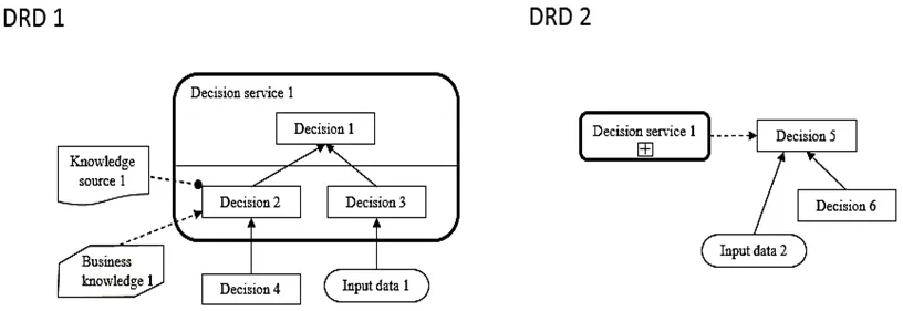
That advantage, however, is offset by a new modeling issue. DMN 1.2 added a “collapsed” graphical shape for a decision service, an opaque rounded rectangle with a [+] marker, in addition to the original “expanded” shape enclosing DRD elements comprising the service. Both shapes reference the same semantic element, the service. For example, in the diagrams above, DRD1 shows the definition of Decision service 1, with parameter names Decision 4 and Input data 1, while DRD2 shows invocation of Decision service 1 by Decision 5 by mapping its inputs, Input data 2 and Decision 6, to the service parameters Decision 4 and Input data 1.
While the spec does not insist on this, it is most natural to use the collapsed shape to show invocation of the service and the expanded shape – in a separate hyperlinked diagram – to show the service definition.
But here is an important difference between a BKM and a decision service. A BKM owns its parameters, so there is no need to worry about name conflicts between a BKM parameter and other model variables. That is not the case with a decision service, notably one that is defined and invoked in the same decision model, as in this usage pattern. A decision service is an overlay. It does not own its parameters, so there is potential for conflicts between the parameters in the service definition diagram and variables in the service invocation diagram. I think the safest thing to do in this situation is to give service input parameters names distinct from normal variable names, so name conflicts cannot occur. This technical issue, I believe, largely offsets the business-friendliness advantage of decision services over BKMs in this usage pattern.
Usage Pattern 5: As a unit of composition
I don’t believe this usage pattern is illustrated or discussed in the spec, so I’m not 100% sure it is allowed. In this pattern the service is not used as a unit of execution nor is it invoked. It is simply a graphical device for hierarchical modeling, similar to a subprocess in BPMN.
When modeling a complex end-to-end decision it is common to break down the top-level decision into a small number of supporting decisions, which are then further decomposed until you have a complete DRD revealing fine details of the logic. But once you have 20 or more nodes in the DRD, the diagram becomes hard to manage or even understand. What you’d prefer is a way to take a fragments of that DRD and collapse it down to a single node – a collapsed decision service – the contents of which would be revealed using the corresponding expanded service shape on separate hyperlinked page of the model. This is exactly how hierarchical modeling works in BPMN. Instead of having to create separate high-level and detailed models, it lets you create a single semantic model supporting both high-level and detailed views of the logic.
In this usage pattern, the service is not invoked, so its parameters must exactly match in the definitional and invocational views – not only in name, but DRG element type (i.e., input data, decision, decision service) and datatype as well. That is because the shapes on corresponding pages reference the same semantic elements.
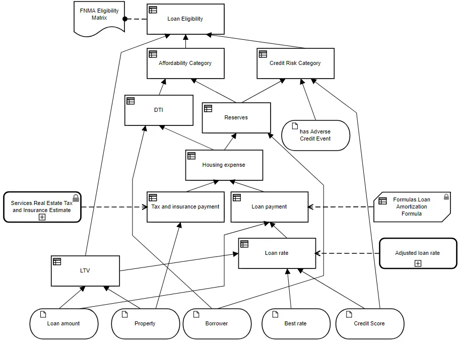
Here is an example from my DMN training. The DRD here shows eligibility of a loan for purchase by FNMA. Already it contains examples of usage pattern 3 (Tax and insurance payment and Loan payment) and usage pattern 4 (Adjusted loan rate), but the bottom half of the DRD could be considered “details” we’d like to hide in the high-level DRD. We’d like to create DTI service and Reserves service to do this via usage pattern 5.
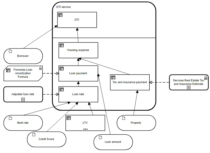
The Trisotech tool provides a wizard alternative to selecting service outputs and encapsulated decisions graphically. Here is its definition of DTI service:
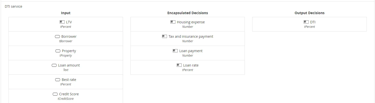
Having created the two new services in this way, we can drag them onto the DRD, replacing DTI, Reserves, and the encapsulated decisions of the services. It now looks like this:
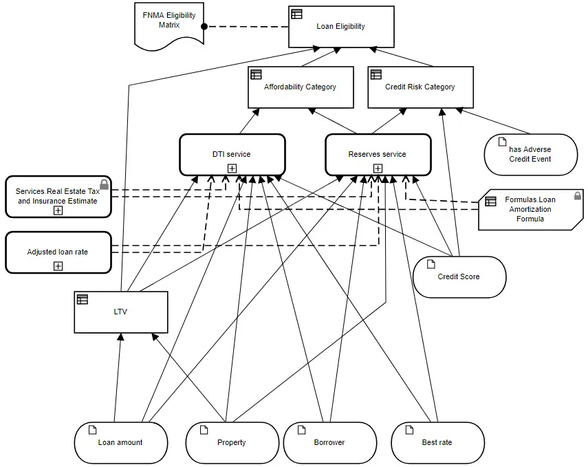
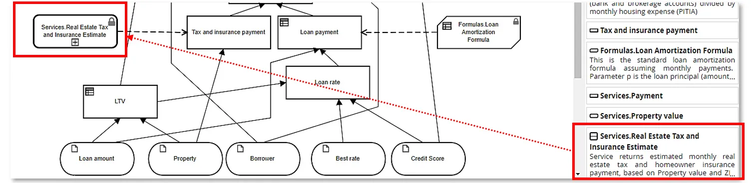
Whether or not you consider this high-level view simpler, given the concentration of information requirements and knowledge requirements, is up to you. Note that our new services are not invoked – they have no outgoing knowledge requirements – although they invoke services and BKMs themselves. Clicking on the [+] in the service opens up the definition view on a hyperlinked diagram, as shown here:
The Bottom Line
Decision services are bound to play increasingly important and versatile roles in DMN models. Tool support for them is brand new, so best practices will have to evolve with more experience.
The post 5 Decision Service Usage Patterns appeared first on Method and Style.